Title

While the main focus of the Strathspey Railway is running steam trains for the paying public, a small but dedicated group of volunteers has been restoring other items of heritage interest in spare moments between working on the loco fleet and improving locoshed infrastructure and facilities.

The current project is a Ruston Hornsby 48DS diesel shunter of 1948 which worked at Longmorn distillery until 1980 (even though Dr Beeching had closed the adjacent main line in 1967). Because it was presented to the Strathspey Railway repainted with advertisements for Queen Anne blended scotch whisky, it is known to most people as “Queen Anne”.

To find out more about our aims, follow this link or click the [About] button above.

This Blog was started over 5 years after the project began, so most of the initial blog entries are retrospective.

Friday, 24 October 2025

Queen Anne at Rail 200 Event at Boat of Garten

The Strathspey Railway held a Rail 200 Event in October 2025.  The specail Rail 200 Exhibition train was stationed at Boat of Garten on the 16th and 17th and a Gala Day was held on Saturday 18th featuring an intensive timetable involving all 3 steam locomotives and all 3 main line diesels.  Cab rides were also available on Queen Anne and diesel shunter D3605.

 Trip to Boat of Garten Monday 13th

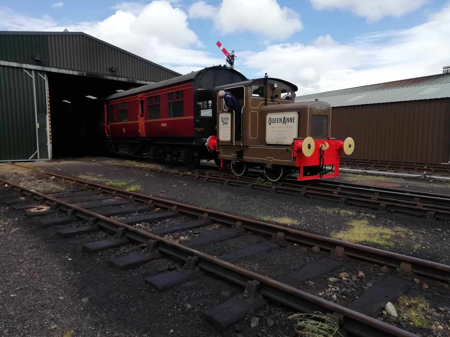
After a thorough wash and polish, Queen Anne was towed at a steady pace from Aviemore to Boat of Garten by diesel locomotive 37674 and placed in the bay platform, ready for duties later in the week.


A shiny Queen Anne in Aviemore ready to go to BoG


Queen Anne arrives at BoG

The Footplate Crew

Rail 200 Exhibition Train

Queen Anne played an important part in the visit of the Exhibition Train.  Apparently the train coaches have an unusual type of handbrake which can sometimes jam on.  To get over this possible problem, they prefer to park the train with the handbrake off and coupled to a locomotive with its own handbrake.  Thus the train was placed in the bay platform at the buffer stops and Queen Anne was stationed at the head of the train with its handbrake on.  There is a slight gradient toward the buffers so the exhibition train would definitely not be going anywhere.

Queen Anne at the head of the Exhibition Train
 

The Exhibition Train departed on Friday 17th for its next stop at Aberdeen.

Footplate Rides at the Saturday Gala

On the Saturday, Queen Anne was stationed in the now vacant bay platform and provided footplate rides up and down the length of the platform throughout the day.  There was no charge but it was suggested that participants could make a voluntary donation for locomotive restoration.

The footplate rides were well received and donations totalling £120 were taken.


Queen Anne at the Stop Board

Ready to return to the buffer stops

Footplate Crew

Queen Anne and BoG Shunter D2774

Here are some videos of the footplate rides :-


Return to Aviemore Monday 20th

One small step for a diesel, one giant leap for Rustonkind.... 

It was decided that Queen Anne would return to Aviemore under her own power.  This certainly would be the longest non-stop trip she has ever made, as the distance is about 5 miles and the rail network at Longmorn distillery was much shorter than that.

Not many Ruston 48DS shunters can have travelled so far in a single journey.

Everything went well and the journey was made in 26 minutes at an average speed of 10 mph, which is the top speed for a 48DS.

This video shows starting up, passing the Kinchurdy foot crossing, going over the level crossing at Dalfaber (Aviemore) and arriving at the yard in Aviemore. 


Back home outside Aviemore Locoshed


Thursday, 12 September 2024

Latest Videos

Test Runs

Two new videos have been uploaded to Youtube.  The first shows the initial start-up and moves in the carriage storage shed.  The second shows a brief loaded test run behind Aviemore signalbox hauling the LMS Officer's Saloon.  There are also links to these videos on the "Queen Anne Videos" page of this blog.


Video #1


Video #2

Thursday, 22 August 2024

Back in Action

Apologies for the lack of updates but gearbox was put back together and tested in June. 

Relined Clutch Plates

The clutch plates were sent to the company in Cumbernauld for relining.  The new linings were riveted on just like the originals.

On return, the linings needed to be skimmed to fit between the steel plates either side that are pushed together to clamp the friction plate.  Unfortunately the Ruston manual does not give any details of the correct thickness.  However they do give details of a gauge to check that the plate spacing is even all round which suggested the gap should be between 0.810" and 0.840".  The gap between the disks is not easy to measure once things are assembled, but the actual gap was less than this - there had obviously been subtle design changes since the manual was written.

Slow and Medium Clutches

Relined Fast Gear Clutch in Place
 

The clutch plates were carefully set up in a lathe and skimmed.  By a bit of trial and error the optimum thickness was determined to be between 0.780" and 0.790".  The process of skimming is also useful in minimising the effects of warping of the steel clutch disk - this can and does happen due to overheating when in use.  This of course depends on the plate being set up in the lathe chuck to rotate about the same axis as in the gearbox.

Once the clutch assembly was back together the clutches could be turned by hand although some friction drag could be felt because the plates had been skimmed to leave maximum friction plate thickness.  Hopefully the clutches will bed in once in use.

Meanwhile the gearbox casing had been cleaned and was ready to receive the refurbished clutch assembly.  Fitting was the reverse of removal, again using the forklift to lift the assembly into the cab.  After that it was manually lifted into position in the lower casing.

Fitting the Strap


On the Forklift

Manoeuvring into the Cab

Clutches Back in Place

Underside of the Top Cover
 

With new gaskets made the top cover was lowered into position and bolted up ready to be filled with oil and tested.  The clutch adjustment springs for each gear were adjusted so that the "pull" required to engage each gear via the lever was the same, and not excessive.

Gearbox Dipstick

The Ruston gearbox is a slightly strange arrangement with separate compartments for the main gearbox and the transfer gearbox (which turns the axis of rotation 90 degrees and contains the forward and reverse dog clutches).  The two compartments have different oil levels and are not connected, although oil does get through the bearing between them.  On Queen Anne's gearbox there are no dipsticks but there is an equalising valve that lets excess oil drain from the main (upper) gearbox to the transfer (lower) gearbox.  The lower gearbox has a tap on the side corresponding to the correct level of oil.  To get the correct level, you must put too much oil in the main gearbox and then open the tap - when oil stops coming out, the level is correct!

To improve on this, it was decided to make a dipstick for the transfer gearbox.  There is no way to place a dipstick on the gearbox casing that is easily accessible, so it was decided to use a Manometer arrangement to locate the dipstick somewhere more convenient.  To avoid machining the gearbox casing (which would risk getting metal swarf inside) the drain plug was extended by a "Banjo Union" arrangement which permits a pipe to be fitted to connect with a separate tube for the dipstick.  The oil levels in the gearbox and dipstick tube should then be identical.  The following pictures explain how this arrangement works.

Banjo, Dipstick Tube and Dipstick

Banjo, connecting pipe and Dipstick Tube

The top of the Dipstick Tube

As can be seen from the photographs, the gearbox dipstick is on the left-hand side of the engine and easily accessible via the bonnet door.

Initial Tests

Although Queen Anne had not run for nearly a year, and the battery had not been charged, it started first time.  The loco was in the carriage storage shed between the crane and the LMS Officer's Saloon.  There was enough space to run up and down between these two to test the clutches.  It was noted that there was some residual drag in neutral which made the forward and reverse gearbox engage with a "clunk".  This should improve as the friction plates bed down.

A few weeks later while the crane was out of the shed, Queen Anne was coupled to the Officer's Saloon and driven up and down the siding behind the signal box.  All clutches behaved well and taking off in slow gear with the coach attached was effortless.

Firing up

Back out in the open


A successful test

It is intended to do further tests with Queen Anne hauling various loads around the yard at Aviemore and up to the station and back.  However this needs to be done out of season on a day when service trains are not running.

A video of these tests will be posted shortly.


Sunday, 3 December 2023

Gearbox Refurbishment - Part 3

More Pictures

Here are some more photographs of the internals of the gearbox.

Clutch drum and various bits

Detail of the clutch operating levers

Fast Gear

The fast gear clutch connects the input and output gears (1 to 1 ratio).  The friction plate is gripped between a fixed plate that is part of the clutch drum and a moving plate connected to one set of operating levers. 

The friction disc with its linings

Clamping plates either side

The fast gear friction plate
 

The brown discolouration of the fast gear friction plate is probably due to oil staining and not due to overheating.

Slow Gear

The slow gear clutch shows signs of overheating on various parts.  The spindles that operate the clamping plates are also discoloured at a place where they are adjacent to the slow gear clutch.  The blue colouring indicates that at some time the steel has been heated to around 290 degrees centigrade.


Slow gear clamping ring

Slow gear friction plate and spindles

The other side of the slow gear friction plate

New Friction Linings

 Investigations are ongoing regarding replacement of the friction linings.  There is a company in Cumbernauld that undertakes this type of work.  In fact they have relined a Ruston 48DS gearbox for a group at Prestongrange Mining Museum.

Another group restoring a 48DS at the Chasewater Railway has also given some useful advice.

It has not been decided yet if riveting or bonding of the friction plates is the best solution.


Tuesday, 7 November 2023

Gearbox Refurbishment - Part 2

Gear Assembly Removal

 To remove the gear assembly it was first lifted manually using rope and steel bars sufficienty to enable two poles to be inserted underneath and raise it slightly above the casing.

After that, Queen Anne was towed outside to allow removal via the cab entrance using a forklift.  Strops were used to attach the assembly as closely as possible to the tine of the forklift.  The lower part of the cab entrance is too narrow for the gear assembly to pass through, but it will fit through the upper part.  However it needs to be lifted to the full height of the cab.

Forklift in position

Strops attached

Have we got enough clearance?

Out it comes - no problem


The assembly was then lowered onto a sturdy trolley and wheeled to the Clean Room for dismantling.


Dismantling started

Disassembly

A gear puller was required to remove the ball bearing and roller bearing that form the rear bearing assembly.  Following that the gears can be slid off and the rear face of the clutch drum unbolted.

The next part to be removed is the clutch friction plate for Slow Gear.  On removing the rear face of the clutch drum the friction material was found to have completely disintegrated.  The clutch disc should have a ring of friction material on both sides, held in place by brass rivets.  In fact both friction rings had deganerated into a fibrous mass.  It is amazing that Slow Gear could be made to supply any drive at all.

It seems likely that the locomotive must have been run for some time in Slow Gear with the clutch slipping, causing overheating and breakdown of the friction material.

Friction plate showing the rivets which once held the friction material


The remains of the friction material


Clutch rubbing plate

To engage slow gear the friction plate is squeezed between the moveable rubbing plate (pictured above) and the rear cover of the drum assembly.

A useful description of the operation of this type of gearbox can be found HERE.  It contains colour-coded diagrams showing how power is transmitted in each gear.  The website is run by the Moseley Railway Trust.

Sunday, 29 October 2023

Gearbox Refurbishment - Part 1

Clutch Problems

The Ruston gearbox fitted to Queen Anne has three gears - slow, medium and fast.  The different gears are in constant mesh, but each ratio has its own friction plate clutch.  Gear selection is achieved by engaging the appropriate clutch via the gear change lever.
 
We have known for some time that slow gear is not very effective - its clutch slips.  There is an adjustment for the spring that applies pressure when the clutch is engaged but while this can make the clutch more effective the resulting pressure is obviously excessive.  The friction plates are riveted to steel disks and it is very likely that the friction material for slow gear has worn down to the rivets.

The replacement of the friction linings is part of normal maintenance for this type of gearbox and is described in the locomotive manual.  Other restoration groups have carried out this work and there are companies who specialize in relining friction plate clutches for heritage vehicles.

The whole gear assembly can be lifted out once the gearbox cover is removed and the assembly stripped down on the bench.

Gearbox Cover Removal

Queen Anne has been kept in the carriage storage shed recently so the first step was to get her moved into the locoshed.
 
Queen Anne being manoeuvred into place

On Road 4 ready to start work
 
The first step is to remove the central floor sections - no problem as they are now secured using stainless steel screws/bolts.  Then the gear change unit must be unbolted from the side of the gearbox.


Central floor removed

Once all the nuts and bolts for the gearbox cover have been removed lifting eyes are screwed into the two positions on the top of the cover.  Because the cover weighs 3 cwt it was decided to use two steel bars and four jacks to lift the cover off.  Since the cover needs to be lifted to at least cab floor level, this required "jacking and packing" using wood blocks.

Jacking system in place

Packed up with wood blocks

Poles inserted underneath the cover

Once the cover had been lifted high enough, poles were rolled underneath and the cover lowered onto them.  The cover could then be slid sideways to sit on the floor at the left-hand side of the cab.

The gearbox mechanism

The above picture shows the gearbox assembly.  From left to right, the main components are :-
  • The output gear to the forward/reverse box.
  • Bearing.
  • The input gear from the drive shaft in the gearbox casing.
  • Fast gear clutch operating ring. 
  • Medium/Slow gear clutch operating ring.
  • Drum containing the clutch plates.
  • Gears providing the different ratios.  The lay gear for this can be seen underneath.
  • Bearing.
As can be seen, the whole assembly simply lifts out.  Further updates will be published as work progresses.
 

Monday, 24 April 2023

Chain Oiler and Diesel Gala

The Chain Oilers

The chain oilers have finally been completed.  A drip-type oil pot is attached to a solenoid valve which is energised while the engine is running.  A pipe feeds the oil to a special brush which is mounted on an adjustable arm to spread the oil over the chain.  There are two separate oilers, one for each chain.

The brushes need to be mounted close to the sprocket on the reversing gearbox.  In any other position they would be vulnerable to the chain whipping or movement of the suspension.  There is not much room near the sprockets so mounting them is tricky.

The following photographs show the setup.
 
An oil pot with its solenoid valve

The LH brush. A very cramped location.

RH brush showing the adjustable mounting arm

Excess Fuel Device

In order for the engine to start (especially when the engine is cold), it is usually necessary to squirt more fuel than normal through the injectors to get it running.  To do this a device is fitted to the control rod that regulates the fuel injection pump.  This device is a brass casting with lugs that is lifted up to allow the control rod to move forward and inject more fuel.  Once the engine is up to speed, the governor pulls the control rod back and the device drops down to its working position, limiting the maximum amount of fuel delivered.
 
Often the engine will start to fire and pick up speed causing the device to drop back, but the engine still needs to warm up a bit more and so the engine stalls.  If the device is lifted up again the engine will pick up speed and eventually run on its own.  Except in very warm weather it needs to be lifted two or three times before the engine will run on its own.

The problem with the original arrangement is that the device is not visible unless you peer inside the engine compartment, so you have to feel for it.  The device is close to the fan belt and other moving parts, so you need to know exactly where the device is.  For this reason it was decided to make an accessible lever to operate the device.  A bracket bolted to the engine block was modified to take the new lever and a flexible steel wire was used to pull up the lug on the excess fuel device.

So to start, all you have to do now is to open the right-hand bonnel door and pull down the lever before starting, and possibly pull it down once or twice more until the engine runs freely on its own.

The new excess fuel lever on the front of the engine

The brass casting and its lug is shown in the circle

Diesel (mixed traffic) Gala 2023


This year's Diesel Gala (7th to 10th April 2023) had Queen Anne offering footplate rides in Aviemore yard.  Things were a lot quieter than the 2022 Gala but those that came on board seemed to enjoy the experience.

Queen Anne also did a couple of "taxi rides" to Aviemore station - a first for the loco.  Here are some photos of the event :-

Queen Anne and the Class 31

Class 37 approaching

In the loop at Aviemore Station

And a video on Youtube :-

Queen Anne also features in some other Youtube videos of the Gala.  See the "Queen Anne Videos" page above for links to these.