Title

While the main focus of the Strathspey Railway is running steam trains for the paying public, a small but dedicated group of volunteers has been restoring other items of heritage interest in spare moments between working on the loco fleet and improving locoshed infrastructure and facilities.

The current project is a Ruston Hornsby 48DS diesel shunter of 1948 which worked at Longmorn distillery until 1980 (even though Dr Beeching had closed the adjacent main line in 1967). Because it was presented to the Strathspey Railway repainted with advertisements for Queen Anne blended scotch whisky, it is known to most people as “Queen Anne”.

To find out more about our aims, follow this link or click the [About] button above.

This Blog was started over 5 years after the project began, so most of the initial blog entries are retrospective.

Tuesday 5 September 2017

Recycling of Materials

Recycling at Longmorn

Until about 1949, Ruston 48DS shunters had no doors on the side of the cab.  So driving Queen Anne in winter with a cold east wind blowing across the fields of Morayshire must have been a bit chilly.

When dismantling the cab, we noticed that a curtain rod with curtain rings had been fitted to each side of the cab.  There was however no trace of the curtain.  It looked as though this might have been a modification by the staff at Longmorn.  When the curtain rings were cleaned up on the grit blaster, they were found to be made of copper.

Recently Jim, who works for Forsyth’s (they make most of the copper stills and fittings for Scottish distilleries) caught sight of the rings and recognised what they originally were.  Apparently they are made by winding copper wire onto a former and then slitting lengthwise to produce the rings.  The rings are then linked together to form a piece of “chain mail” about 1 metre square.  This is then fitted inside the copper still and rotated to knock back any foam generated by the boiling wort.
Some of the foam-busting curtain rings
Because the rings form a link with the locomotive’s whisky heritage, the curtains will be reinstated when the cab is rebuilt.

Recycling at Aviemore

A lot of riveting is currently taking place on Aviemore’s Black 5, 5025.  The running boards are mainly held on by 5/8 inch rivets.  These rivets as supplied are about 4 inches long, and have to be shortened to the thickness of the plates plus an allowance for forming the rivet head.  As a result, there are a lot of 2 inch lengths of 5/8 inch diameter rivet-grade steel left over.

These leftovers have been machined into 3/8 inch dome head rivets suitable for Queen Anne’s cab.  Tests have been carried out, and they can satisfactorily be cold riveted.  The original rivets were simply flattened to a “pancake” shaped head on the reverse side, and suitable rivet dollies to do this have now been machined.  Riveting will be done using the hydraulic riveter, which is basically a big G-Clamp with a power-operated hydraulic ram.
Bolts on the left, rivets on the right
The other cab fasteners were 3/8 inch Whitworth bolts with a domed and slotted head.  Whitworth bolts are now very expensive, and almost impossible to get with this type of head.  So new bolts have been machined out of EN316 stainless steel for this purpose.

Other News

Cab Steel

The steel to join together the water-jet-cut steel cab sheets has now arrived.  This consists of angle, flat bar and “half-round feather edging”.  As it will be  a while before we have time to start rebuilding the cab, to prevent the steel from corroding, the angles and flat bars have been cut to length, rubbed down and painted with red oxide primer.  The feather edging has been rubbed down and treated with an oil-based preservative.
Cab strip and angle sections painted

Feather-edge strips with protective oil coating

Battery Box

Here are some pictures of the battery box, which was restored some time ago.  It is currently used to store nuts bolts and other small parts for the locomotive.
Battery Box after cleaning up a bit
The box consists of a compartment for tools etc. on top and a compartment for the 12 Volt battery underneath.  The bottom and lower sides of the box were rotten, the battery compartment door was missing, and the lowest section of T&G board at the back was missing.  The decay was mainly due to the fact that the bottom of the box sits on the cab floor, although it is also bolted to the cab sides.  It is intended to mount the repaired box 1 inch above the floor, possibly with rubber feet to help support the weight of the battery.

The toolbox had been repainted with beige paint, which was removed using a hot air gun, revealing the original “Ruston Green” colour.  The toolbox lid was warped, and was flattened using clamps and a hot air gun.  The rotten lower halves of each side were cut off and new sections attached using a half-lap joint and Gorilla Glue.  A new bottom board was made and reinforced with steel angle brackets so that the box could be fixed slightly above the floor.  All original screws and nails were removed and replaced by brass screws.  A new battery compartment door was made from wood reclaimed from an old T&G door and fitted with new hinges and a catch.  The many holes and imperfections were filled with two-part wood filler and the whole box painted in grey undercoat.

New bottom sections and battery door fitted

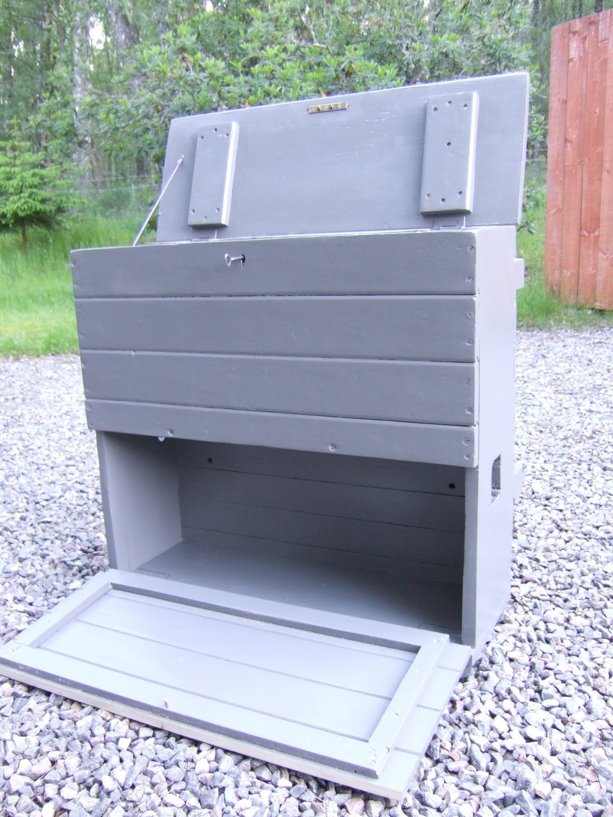
The restored Battery Box
Another view of the box

Engine News


Although the engine runs, it produces a lot of white smoke (unburnt fuel) and this has been traced to cylinder no. 1, which is suffering from low compression.  More details will be given in a future blog.


Friday 16 June 2017

Injectors

The Achilles Heels of earlier Ruston engines are the injectors.  These were of Ruston’s own design and made in-house.  Although they worked perfectly well, they were difficult to service and because they were only used on Ruston engines, there are now very few spare parts left.  Later Ruston engines used CAV injectors, as did most small and medium-sized British-made diesel engines, and hence replacement CAV injector parts are more readily available.

The Ruston Mark 37 Injector

A Ruston Mark 37 Injector from a VPH Engine
The picture shows the components of a Mark 37 Injector :-
A    Plug (overflow pipe connects here)
B    Sealing washer
C    Needle Valve Stop
D    Injector Spring
E    Spring Washer
F    Spring Housing
G    Nozzle Assembly
H    Injector Body with inlet filter
 
The injector nozzle is the most stressed part as it is in direct contact with the hot combustion gases.  It is also very critical as it must produce a spray of very fine droplets of diesel to obtain correct combustion without excessive smoke.  It contains very small holes, which can become blocked, is subject to erosion, and the needle valve and seat become pitted leading to dribbling and poor combustion.  The nozzles are designed to be serviced at intervals and replaced when necessary whereas the rest of the injector will normally last the life of the engine.

The earliest Mark 37’s had a nozzle that was separate to the needle valve and guide and was difficult to line up correctly.  Subsequent injectors, including those on Queen Anne, had a combined nozzle, needle valve and guide which is a much more satisfactory arrangement.  The nozzles are machined to very high tolerances and must be kept scrupulously clean.

The injector pressure is important, and for the Mark 37 should be 3000 psi.  Other makes of injector have a screw device to vary the pressure on the injector spring, but with Mark 37s shims have to be placed alongside the spring washer (E), and this involves repeated assembling, testing and dismantling until the correct pressure is reached.
The Water-damaged Nozzle

The picture shows a nozzle that was badly pitted due to water entering the cylinders when the loco was abandoned.  It is obviously a write-off.  Unfortunately there seems to be no replacement nozzles to be found anywhere, in spite of contacting various specialist companies and Ruston experts.

The Wrong Nozzles

When the injectors were dismantled, it was found that the wrong nozzles had been fitted at some time in the past, presumably at Longmorn.  There was one of the correct type (VRH) and three for a VPH engine, which has double the cylinder volume.  The VRH nozzles have 3 x 13 thou holes and the VPH nozzles have 4 x 16 thou holes – quite a difference!!!
You can see the wording FVPH on the left and FVRH on the right.  Also showing the needle valve.

The engine obviously ran with VPH nozzles, and as VRH nozzles are unobtainable it was decided to use VPH nozzles in all injectors.  This meant replacing the VRH nozzle and badly pitted VPH nozzle.  Of course, VPH nozzles are unobtainable too, so it was decided to “borrow” nozzles (also in poor condition) from the out-of-use Ruston 0-4-0 DM shunter, which has a 6VPH engine.

Reconditioning

Two tools were made to aid in dismantling the injectors.  A simple removal tool screws into the Needle Valve Stop (C) and pulls it and the washer (B) out.
Simple Dismantling Tool

The orientation of the injector sprays is important, and an inscribed line on the nozzle must line up with a similar line on the injector body.  A special tool was made to allow all the injector internals to be lined up before sliding the injector body over.
The Assembly Jig

Injector Internals Mounted on the Assembly Jig

The injectors were reconditioned by Rayner Diesels in Newbury.  While they normally service modern diesel fuel injection equipment, they have many years expertise and still have the equipment and knowledge to service older injectors.  For injectors in such a poor state, renewal of the nozzles would be the normal solution, but in the absence of spare parts the nozzles had to be brought back to life.  The needles were seized in the nozzles and needed to be warmed up gently to soften the congealed diesel oil.  The valve seats were badly pitted and needed carefully lapping in with very fine grinding paste.  Most of the nozzle holes were blocked up.

The sealing washer (B) is a special shape as it needs to seal both the needle valve stop (C) and the injector body (H) against the full injection pressure.  These washers can only be used a limited number of times, so some new ones were machined out of copper bar.  Rayners were short of one good washer, so one of the injectors suffers from back-leakage until we have made and fitted a new one.  This should cure the white smoke which is currently being generated by No. 1 cylinder.


If anyone knows of a source of Ruston Injector Nozzles, please let us know.

Tuesday 14 March 2017

Engine Started!

On Saturday 11th March 2017, the engine was started for the first time in about 35 years.  It took took a while to get all air out of the fuel system and get all four injectors firing, but it seems to start reliably now.  From cold, you need to use the "excess fuel" device, but once the engine is warm it starts without this.

The following short video clips record the event :-

First run

Running continuously now

Friday 10 March 2017

Spragging Gear


Spragging Gear

Spragging Gear is the name used by Ruston to describe the exhaust valve lifting mechanism that allows the engine to be turned without compression.

The spragging gear helps in starting the engine.  The crankshaft can be rotated much more rapidly (using the starter motor or by hand) if there is no compression.  When the gear is released, the momentum of the flywheel helps to maintain speed while the engine starts.  If the injectors or pump are worn, the initial rotation will prime the injectors and ensure that fuel is being delivered when compression begins.  In favourable conditions, it might be possible to start the engine by hand using this method, although it would require considerable stamina and probably the use of both winding handles (located on either side of the loco).

Each cylinder head has a side cover which carries the spragging gear.  A cam is rotated through 60 degrees and lifts an operating rod by about 80 thou to push against the exhaust valve rocker and open the valve.  The following diagram from the Parts Manual shows the general arrangement.
Spragging Gear Parts for a Ruston 4VRH
Because the gear spends most of its time inactive, it appears to have been under-designed by Ruston & Hornsby.  The cams had become very loose in the covers (there is no effective lubrication for the bearings), and there was a lot of wear in the operating mechanism.  Also the operating levers on each cam had been pinned at inconsistent angles, so the cams were not properly aligned.  The sprigging gear should be set so there is a 25 thou gap when the gear is inactive and the exhaust valve closed.  However because of wear, there was 40 thou of slack, so proper setting was impossible.  In fact, prior to restoration, the gear had been adjusted to a large gap, effectively putting it out of use.

The bearings in the covers were bored out, fitted with bronze bushes and reamed to size.  The bushes have a groove to take an O-ring seal and an oil hole to allow engine oil to drip through.  New cams were made as the old ones had worn bearing surfaces and worn cam profiles.
Cover with new bush.  New cam on left, old one on right
The operating levers for cylinders nos. 2 and 3 have a slot in the end to allow for slight differences in height.  However, these slots had become worn, so it was decided to make new ones to remove the slack in the operating mechanism.  The long lever on cylinder no. 1 had a crude stop on it to define the two positions (30 degrees either side of vertical).  This had become worn and imprecise, so a new rod was made with an improved design for the stops.
Two new levers.  One old lever.  Two refurbished levers.
Once the improved gear is in place, another attempt will be made to start the engine.
Top view of the engine with new Spragging Gear in place.

Filters

The original Ruston 4VRH engine had mesh/felt filters for oil and fuel.  These filters are not very effective and are messy to strip and clean.  A decision was made to replace them with modern cartridge filters, which are much more effective and because they are easy to change they are more likely to be changed regularly.  An additional water trap was installed on the fuel line as fuel quality cannot always be guaranteed.
New Water Trap and Fuel Filter
In order to make things as original as possible, the upper parts of the filter brackets were retained and adaptor plates made to accommodate the new screw-on filter elements.  The Ruston manual calls for an SAE20 or SAE30 detergent oil for the engine, and the use of a modern oil filter means that modern oils can be used – in this case Morris ring-free XHD30.  Diesel engines generate quite a lot of carbon past the rings and into the sump, so a good detergent oil keeps this in suspension and prevents sludge building up.
The new Oil Filter

Radiator & Fan Belt

The radiator consists of three parts; the upper tank (steel), the core (steel) and the lower tank (brass), which are bolted together with rubber gaskets.  Fortunately the steel core seemed to be OK after cleaning up.  New gaskets were made and the radiator tested for leaks.  The bottom tank was found to be leaking around the bolt holes.  This was traced to hairline cracks in the brass, and these were repaired by brazing.  The inlet and outlet pipes were badly corroded inside, and were not particularly well soldered. so these were replaced by new stainless steel pipes.

Subsequently the filler pipe started leaking around its joint with the upper tank.  It is vulnerable while the radiator cowl is not fitted and had probably been strained.  It was found to be rather crudely soft-soldered to the tank with only a steel wire ring underneath for support.  Because the pipe itself was badly corroded inside, it was decided to replace the pipe and secure the new one using large brass nuts and sealing washers.  The original filler cap was worn and would only engage on a few threads, so a new one was machined out of brass.

The original reinforced rubber hoses were replaced with new polyurethane hose, which is much more durable.  It was decided to incorporate a water level indicator.  This consists of a standard steam loco “gauge glass” tube contained in a machined brass holder and has been fitted next to the thermostat.
Radiator, water gauge and fan belt
The fan belt has been fitted and tensioned.  The belt is of the “link belt” type because it would not be possible to fit a standard belt without removing the bevel gears on the front of the crankshaft that comprise the hand winding mechanism.  In any case, the pulley profiles are of an obsolete type, and modern belts would not fit properly.  Indeed modern link belts are of the wrong profile too, but some suitable “Brammer style” link belt was obtained from Stationary Engine Parts.