Title

While the main focus of the Strathspey Railway is running steam trains for the paying public, a small but dedicated group of volunteers has been restoring other items of heritage interest in spare moments between working on the loco fleet and improving locoshed infrastructure and facilities.

The current project is a Ruston Hornsby 48DS diesel shunter of 1948 which worked at Longmorn distillery until 1980 (even though Dr Beeching had closed the adjacent main line in 1967). Because it was presented to the Strathspey Railway repainted with advertisements for Queen Anne blended scotch whisky, it is known to most people as “Queen Anne”.

To find out more about our aims, follow this link or click the [About] button above.

This Blog was started over 5 years after the project began, so most of the initial blog entries are retrospective.

Wednesday 14 December 2016

Gearbox and Transmission

Gearbox and Transmission

Thanks to the generosity of the Friends of Broomhill Station, we have received a donation that has enabled us to buy a new drive chain.  Fortunately 1.5 inch pitch heavy-duty roller chains are still available.
The new drive chain
 The power from the engine is taken via a flexible coupling next to the flywheel to the Ruston patent constant-mesh gearbox, which has 3 speeds.  This feeds the integral transfer gearbox, which moves the axis of rotation 90 degrees and is equipped with a forward-neutral-reverse lever.  The output shaft, running across the gearbox, has a sprocket at each end driving the two axles via roller chain.  The axles are suspended from adjustable-length swinging arms, whose pivots are approximately (but not exactly) in line with the transfer gearbox output shaft, so that the chain tension does not vary too much as axles move up and down.  The adjustable swinging arms allow wear in the chains to be taken up.
The new chain in place, before adjusting the tension
The Ruston patent gearbox was designed in 1931 and used in almost all narrow-gauge and the smaller standard-gauge shunters with chain drive.  It proved to be a robust and reliable transmission.  Each gear ratio has its own friction clutch, and a system of interlocking selector levers ensures only one clutch can be engaged at a time.

It was noticed that the gearbox input shaft on Queen Anne had some side play, so the top gearbox cover was removed (it weighs 3 hundredweight).  The input shaft runs in the upper cover supported by a ball bearing and a caged roller bearing.  The ball bearing was not the original, and at some time in the past the shaft had been rotating inside the bearing.  The roller bearing also seemed a bit noisy, so both were replaced with new British-made bearings.  The worn shaft was built up with weld and machined back to the correct size.  An extra rubber shaft seal was also fitted to prevent dirt entering the ball bearing.

The gearbox was also given a good clean out.  Because it uses friction clutches, a lot of grey sludge is formed as the friction linings wear.  Also the flange that joins the two parts of the casing had been damaged in the past and a corner bolt-hole had broken.  A crude bracket held the broken part in place.  The broken pieces were welded back using an arc welder and pure Nickel rods.
General view of the gearbox
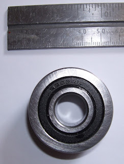
The gear selector mechanism bolts onto the side of the gearbox.  A roller on the bottom end of the lever depresses one of three tappets that select the appropriate gear.  The roller and its pin were badly worn (their position means that they are unlikely to get any lubrication), so initial thoughts were to make replacements in silver steel and harden them.  But after some thought it was decided to use a Cam Roller which is a special sealed ball bearing designed to be used for this purpose.  A new pin was made to hold the roller in place.  After fitting the roller, it was found that the gear lever could easily be made to spring back into neutral – it would be very painful to be hit by the lever as it springs back.  The roller is designed to go over “top dead centre” and be held in the engaged position by the tension of the clutch springs, but on investigation the tappets were found to be slightly worn so that the roller was barely going over top dead centre.  Dressing the tappets with an abrasive flap wheel restored the correct profile and resulted in firm engagement of the gear lever.
The original worn roller
The new Cam Roller

The Cab Floor

The cab floor consists of several steel panels which bolt together.  The original design used nuts and bolts in some places, which meant access to both sides was required to remove sections of floor – essential to gain access to the gearbox etc.  So it was decided to ensure all fixings were via countersunk screws that fitted into tapped holes in the supports.  Stainless steel screws were used to prevent them from seizing up.
Some of the floor panels and the fuel tank after painting
While parts of the floor were supported on brackets on the chassis, the edges were originally supported by the cab sides, which in turn were attached to the chassis by a metal plate which was a rust trap.  This arrangement was re-designed to use four pillars rising from the chassis at each side to support the floor close to the edge.  Not only does this produce a more rigid floor, but the floor can now be a solid stand-alone platform without needing the cab to be present.  Also the rust-trap at the bottom of the cab sides can be eliminated and be replaced by a simple stiffening bar.
View showing the 4 vertical pillars towards the back
 The floor panels were bolted down with rubber pads underneath to reduce vibration.  In future it should be a simple matter to remove a section of floor for maintenance purposes by undoing a few stainless steel screws.
The outer floor panel is screwed to the 4 pillars

Latest News

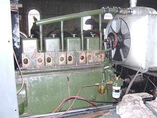
Here is a recent photograph showing the cylider heads in place and the reconditioned injectors fitted.
A view of the engine


Thursday 1 September 2016

New Owner's Plate, Nameplates etc.

Owner's Plate

If you look at the black-and-white photograph at the top of the blog, you may be able to make out a small sign fixed to the lower bodywork of the locomotive.  After purchasing a full-resolution copy of the photograph and blowing it up, it can be seen to be an owner's plate.
Detail of the side of the locomotive in 1977
It reads "Ms. Longmorn Glenlivet Distillers Ltd." - the "Ms." stands for Messers.  The plate is long gone, but by measuring the distance between the empty bolt holes on the locomotive (15 inches apart) it is possible to work out the size of the lettering etc.  A desktop publishing program (Scribus - it is free open-source software) was used to produce artwork to match the original :-
Artwork for the Owner's Plate
Kingussie High School has been very generous in allowing us to use some of the equipment in the Technology Department, namely the CNC router and the casting furnace.  The artwork was used to produce a pattern in MDF using the CNC router.
Casting patterns in MDF
The pattern is placed in a wooden frame known as a flask, and oil-based moulding sand compacted firmly around it.  The easiest and quickest way to cast something like this is to use an open mould, and simply pour molten metal (Aluminium in this case) into the flask after removing the pattern.  However, the quality of the resulting castings was not very good.
First attempt at casting
The metal has not flown fully into the lettering, and shows a meniscus instead of sharp edges.  The reason for this is that there is not enough pressure to force the molten metal in - the pressure is only about 15mm of Aluminium.  The answer is to take more time and use a two-part flask.  The pattern is first placed in the lower part (the drag) and packed with sand.  It is then turned over and the upper part (the cope) placed on top.  Pipes are fitted to produce risers for the molten metal to flow in and out.  The cope is then packed with moulding sand and the cope is lifted off the drag.  The pattern and pipes are removed, everything is cleaned up and the cope is re-fitted.  Molten Aluminium is then poured into the flask until it appears at the vent.  The greater height of metal gives a higher pressure - about 100mm of Aluminium.  The result is much crisper definition.
The Drag and Cope ready for pouring

Pouring the molten Aluminium

Cope and Drag separated after the metal has solidified

Nameplate before removal of the sprues

The final nameplate cleaned up and ready for painting

Nameplates

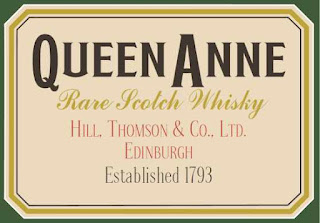
The same process was used to make the nameplates.  The artwork was based on the font used in the original Queen Anne advertising panels, and truncated corners were also used for this reason.
The finished nameplates

Worksplate

All Ruston locomotives have a worksplate with the works number of the locomotive.  Unfortunately, this had been stolen by souvenir hunters while the locomotive was dumped behind Aviemore Speyside station - or it may have been removed for safekeeping, but if so where is it?  The lower front cab panel shows the marks where this and other instruction plates were originally.
Location of missing plates inside the cab
Fortunately, a picture of a worksplate from a Ruston 48DS of similar vintage appeared on an auction site, so the artwork could be reproduced.
The technique for producing the worksplate is quite different and involves etching the design onto a piece of sheet brass.  The artwork is produced in negative format - that is black background and white letters.  This is then printed onto a transparent sheet using a laser printer.  The brass blank is covered with UV-photosensitive resist.  Spray-on resist is no longer readily available but self-adhesive film from China is very cheap (even including postage).  It takes a lot of practice to apply the film without air bubbles, but it can be done.

The negative is placed over the resist-covered brass plate and exposed to strong sunlight for 5 minutes (not much of that this year).  Afterwards the unexposed resist is washed off with some of the developer powder dissolved in water (the instructions are all in Chinese).  To etch the brass away, Ferric Chloride is used.  Fortunately an etching kit designed for making your own printed circuit boards and dating from the days of "Practical Electronics" magazine was to hand.  The etchant had not gone off, and after an hour or so (to get a really deep etch), the plate was removed and cleaned.  A proprietary brass blacking solution was used for the background.
The finished worksplate
The Size, Class and works number will be stamped onto the plate at a later date.

As can be seen from the picture of the cab panel, there were also 3 rectangular plates inside the cab that gave instructions on the driving the locomotive.  The text for one of these has been recorded from an online photograph, and the text for the other two will be investigated.  If anyone knows who has the originals, please let us know.

Tuesday 19 July 2016

Colour Scheme


The choice of livery for a locomotive can be controversial and the cause of much heated argument among railway enthusiasts.  Hopefully the proposed livery for Queen Anne will not stir up too much trouble.

As can be seen from the image at the top of the blog, QA has panels advertising Queen Anne whisky on a strange beige coloured background with white lining.  An earlier colour photograph shows the same adverts against a greenish background, but with subtly different lining, so the background must have been repainted at some point.  It is likely that the locomotive never ran at Longmorn with this colour scheme, but was painted specially for delivery to the Strathspey Railway in 1980.  QA was delivered to Longmorn painted in green with white lining and white buffers, and ran in this state until 1980 when the distillery’s private rail network closed.

Pure Ruston

While many industrial customers for Ruston & Hornsby’s locomotives would ask for their loco to be painted in their company colours, it appears that the distillery did not specify any such colour scheme, so the locomotive was delivered in R&H’s own standard livery at the time (1948).  This consisted of “Ruston Green” (also known variously as Lincoln Green or Verdigris Green, BS381C Shade 276) on most of the locomotive and inside the cab with white lining, red buffer beams (exact shade unknown) and a black cab roof.  There was a Ruston & Hornsby crest on the side of the cab, and RH monograms inside the cab.  The green background at the top of this blog is "Ruston Green".

There are sufficient black & white photographs of the locomotive at work at the distillery to re-create the white lining.  Some “paint archaeology” has exposed the original crest on the cab sides so that its size and position could be determined.  No colour photographs of the locomotive at work have been found so far.
Side of cab with paint removed to expose original Ruston Hornsby crest
The original Ruston crest on the cab side exposed
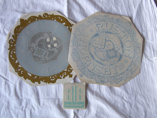
Picture of new Ruston Hornsby transfers for Queen Anne
Some original Ruston transfers have been purchased for the cab
There are quite a few Ruston 48DS locomotives in existence, although only a few are in working order, and none are in pure Ruston livery.  This is another good reason to restore Queen Anne as closely as possible to its as-delivered state.The locomotive never carried a number or name while at Longmorn, but since arriving at the Strathspey Railway it has been known as Queen Anne because of its advertising panels.  For this reason it has been decided to cast Queen Anne nameplates to be fitted on the upper bonnet of the loco.  For those people wishing to take photographs in completely “Pure Ruston” condition, they could be removed temporarily in exchange for a £20 donation to locomotive restoration.

The Queen Anne advertising panels have been photographed and reproduced using desktop publishing software.  The artwork is in the form of actual size print-ready PDF files, so could easily be printed as self-adhesive vinyls or magnetic sheets at fairly low cost.  So it would be possible to temporarily create something approaching the “Queen Anne” of the 1980s if required.

Original Queen Anne advertising panel in rusted state
Original Queen Anne advertising panel
Reconstructed artwork using best-match modern fonts
Hopefully reverting to the original livery will appeal to those who would like to see an accurate restoration of a distillery shunter as well as fans of Ruston & Hornsby locomotives.

Latest Updates

The reconditioned cylinder heads have now been put back on.

The Ruston 4VRH engine on 16th July 2016

The right hand side of the engine on 16th July 2016
Also, the GNSRA article on Queen Anne can now be seen on the "Queen Anne History" page.

Friday 8 July 2016

Latest! Cab sheets arrive.

While the other posts on this blog have been recapping what has been done in the past, this post relates to progress right now (July 2016).

It would be feasible to make new sheeting for the cab in-house by plasma-cutting, hand-finishing with an angle grinder, marking out and drilling holes.  However this would require a lot of time and effort, and it would be difficult to get really straight vertical edges where the sides are joined on with angle iron.  It takes much less physical effort to measure up the old cab sheets and produce drawings in AutoCad.  CAM (Computer Aided Manufacturing) can then produce new cab sheets with a high degree of accuracy an no hard work!
A CAD drawing of the cab sheets was produced after careful measurement of the old metalwork.

Upper & Lower Cab Front CAD Drawing
There are three main ways of producing metal sheets using CAM; plasma, laser and water jet.  Plasma cutting is the fastest, but is less accurate and requires some finishing.  It is not very good for cutting small holes (eg. 10mm), but you can use it to produce a shallow cross to mark hole centres.  Laser cutting is very accurate and requires little finishing.  It is also good for fine detail and holes.  Water jet cutting is often used for cutting thick materials, but is also good for sheet metal.  It is a bit slower than the other methods but very accurate.  Because there is no heat-affected area around the cut, there is no distortion and no finishing is required.  Water jet cutting uses a very fine jet of water at 60,000 pounds per square inch pressure, either with or without an abrasive (depending on the material).

Initial thoughts were to use plasma or laser cutting, and there are companies that can do this in Aberdeen and Glasgow.  However a recent volunteer at the locoshed is a machinist at Forsyths in Rothes.  While Forsyths traditional market was making and maintaining whisky stills, they also do specialist work for the oil and gas industry, and have a water jet cutter.  Jim took away a memory stick with the AutoCad drawings, and most unexpectedly a couple of weeks later the new cab sheets arrived at Aviemore sheds!

Upper rear cab

Lower front cab

Lower cab sides

The finish is truly amazing, and the cut edges are perfectly straight with no burrs.  They arrived as bare metal, so were immediately sanded and professionally painted with red oxide primer.  It is important to apply primer carefully (avoiding sags and brush-marks) to make life easier when applying the final coats.  Otherwise it would require a lot of sanding down to obtain a good finish.

Detail showing clean edges and neat holes

This slot (for the spragging lever) shows the precision of the cutting process

Lesson Number One

Assume nothing.  There are 4 "identical" handrails on the sides of the cab, and on the CAD drawing the fixing holes are all the same distance apart, based on the measurements of one old sheet.  However, it appears the handrails were not accurately made and differ in length by a few mm, so the original cab sheets must have been drilled to fit the handrails.  Some dressing of the holes will be required, but it won’t be noticeable when the handrails are fitted.  This is the first job using CAD/CAM, but there can be no excuses – what you get is only as good as the drawing!


Friday 24 June 2016

The Electrical System

The Ruston 48DS has a very simple electrical system consisting of a 12 volt battery, front and rear facing spotlights, a cab light, a horn, a dynamo and a starter motor.  The Control Box in the cab has 4 pull switches for the lights and starter, a keyswitch, a dynamo warning light and a 2-pin socket for an inspection lamp.  Needless to say all of this was in a very poor condition.

Some of the electrical parts, including a very corroded control box
 Everything was wired up with brass-bound armoured cable.
The armoured cable, along with one of the horn push-buttons
Unfortunately, the rubber insulation had perished creating short-circuits and was unusable.  New armoured cable is available from suppliers of parts for classic car restoration.  Replacement cable bound with Aluminium would cost about £100, and brass-bound cable approximately twice that.
 
Inside view of the rebuilt CB


An "R" needs to be engraved on the second button (Front, Rear, Cab lights and Start)
A new Control Box was made from steel sheet, silver-soldered and painted.  The design was altered so that the front panel could be removed without the whole box becoming loose (hence the brass pillars).  Ruston made good use of Lucas parts in their electrical systems.  Fortunately when Lucas CAV closed down, much of the tooling was bought up and many old parts are still available (although made with modern plastics rather than Bakelite).  The new parts are the fuse holder, the junction box, the keyswitch and the 2-pin plug and socket.  The pull switches were repaired by cleaning up the contacts, but new knobs had to be bought to replace the missing originals.
The front and rear lights, the cab light and a new horn push-button
The spotlight on the left is an original that has had corrosion repairs and has been refurbished.  The light on the right was from a tractor, and has also been refurbished.  The other original spotlight was too corroded to be repairable.

The cab light glass was smashed.  However a clear glass lens of almost the correct size was used in Minis and other BLMC cars, and was still available.  Its diameter was slightly less, so a new retaining ring was machined in EN316 stainless steel with a very fine thread so that it screwed onto the original fitting.

There are two horn buttons, one on each side of the cab, but neither was serviceable.  Again, new identical Lucas parts are still available and one of the new push-buttons is shown alongside its box.
The horn with its new cover

It says "CLEAR HOOTERS".  It isn't particularly loud, but you'll have plenty of time to get out the way.
The horn had a cover to keep out the rain, but it was crudely made from thin steel sheet.  A more robust cover was made from a section of steel pipe.
The refurbished dynamo
The dynamo was made by CAV and originally had a CAV regulator fitted.  However this must have been replaced while at the distillery with the familiar Lucas type fitted to many cars of the 1960s.  It still uses the original mounting bracket.  The dynamo seems to be in good order and only needed cleaning and new wiring.
The refurbished Oil Pressure Gauge
This isn't an electrical component, but it is part of the instrumentation (the only instrument, in fact).  Apart from cleaning up, a new pointer had to be made and a new glass fitted (after at least 3 attempts at cutting a circular piece of 2mm glass).

The starter motor only needed cleaning and rewiring.  The starter solenoid was missing, so an old Lucas one was used and mounted on the starter.

One of the last stages in the project will be to fit all this equipment, but that is some way off.  We still need to buy some of the original type of wire-bound armoured cable before then though.

Tuesday 31 May 2016

Dismantling 2 - Everything but the engine

The cab was suffering from serious corrosion.  The cab consists of several panels of 4mm and 5mm steel joined by angle iron or flat steel strip.  These parts are fastened by a mixture of round-head 3/8” Whitworth bolts and 3/8” round-head rivets.  The cab opening is edged with steel strip known as “half-round feather edge”, which is riveted to the panels.  Rust had formed between the panels and the angle iron and also between the panels and the half-round feather edge, and as corrosion progressed the panels had buckled between fixing points due to the expansion of the rust.  The panels had also corroded through in a few places.  The fact that the panels had been distorted and the extent of the corrosion meant that the panels, angle iron and feather-edge were all scrap.  However they would be kept to provide a reference for making new parts in future.

Before dismantling the cab, the electrical system was removed.  The electrical system is very simple and consists of a control box with a key switch (the control box had been levered open and the key switch stolen) and four push-pull switches for lights (front, rear and cab) plus engine start.  A push-button on each side of the cab operated the horn.  All wiring within the cab used brass-bound armoured cable.  The control box, cabling, switches, lights and horn were all removed and set aside for restoration.  The large wooden tool / battery box was also removed for restoration – the lower half had partially rotted, but it was restorable.
The upper front of the cab, showing the corrosion and buckling at the edges
A few cab bolts were salvageable, but most were removed using an angle grinder.  The roof was the first part to be removed.  Its shaped angle irons and the roof sheet itself were salvageable, but the feather-edge would need to be replaced.  The roof rear end was bent by the chains when Queen Anne was lifted from its siding, but could be straightened.

The lower rear cab panel
The original design of the cab had a horizontal sheet of metal from the lower edge of each cab side to the main chassis girder (this part is below the cab floor).  It was a trap for dirt and moisture and was the most corroded part of the whole locomotive.  This will be redesigned in future to eliminate the rust trap and improve the method of fixing the floor.
Badly designed bodywork
The chassis is formed from substantial rolled steel sections (mainly U-channel) from Lanark steelworks and welded together.  There was some localized corrosion (particularly where the rot-trap above was bolted on) but the substantial nature of the steel ensured it was not a problem.  There was quite a bit of corrosion (and a mummified rat) in the area of the sandboxes.  This was because sand would get spilled when filling the sandboxes and go through the gaps onto the chassis below.  A small part of the chassis was ground back to help any sand drop onto the track.

In one place this corrosion had extended to the nut on the back of the buffer that retains the buffer spring.  Also, one of the fixing bolts for each sandbox is hidden behind the buffer, so all four buffers had to be removed to enable the nut to be replaced and the sandboxes to be refurbished.

The brake gear was stripped off and was basically serviceable (but partially seized), although the pivots that take the brake blocks were a bit worn.

The suspension uses leading and trailing swinging arms pivoted around the centre of the locomotive.  The pivots are approximately coincident with the sprockets that drive the wheels via chains and this ensures that the chain will not come off as the wheels go up and down.  Because the drive sprockets for the front and rear chains are on the same axis, this alignment cannot be exact for both axles.  By making the length of the swinging arms adjustable, the chain tension can also be set.

The axle bearings were found to be in good condition.  A bronze bush spanning 180 degrees of circumference bears on the steel axle which is lubricated by an oil pad.  All suspension parts were cleaned up and put back.  Leaf springs are used, with the upper (largest) leaf bearing on one of the chassis girders.  This allows the springs to move laterally as the length of the suspension arms is altered.  The upper leaf on one of the wheels was found to be broken, but was welded back together.  This spring will be monitored to see if the repair holds.

With everything stripped, the suspension is being attended to
Practically everything was stripped from the chassis, leaving it with just its wheels and the engine block and gearbox still in place.  The long process of examination, refurbishment and reassembly lay ahead.

Friday 13 May 2016

Dismantling 1 - the engine

One of the first jobs on getting Queen Anne inside the locoshed was to determine the condition of the engine.  The "bonnet" superstructure was removed along with the radiator cowl and the radiator to allow all-round access to the engine.

The crankshaft did not seem willing to turn, and on removal of the exhaust manifold and silencer, the latter was found to be half full of water.  The loco has a vertical exhaust pipe and the open end had not been covered when it was laid up out of use, so rainwater had accumulated inside the engine.

An attempt was made to turn the crankshaft using a bar in one of the holes in the flywheel and a jack against the chassis, but it was stuck fast.  On removing the four cylinder heads, it was found that water had got into cylinders nos. 1 and 2 because their exhaust valves had been open.  Cylinders 3 and 4 were dry.

There is another Ruston shunter at Aviemore - a 165 HP 0-4-0 with a 6VPH engine.  This had seized because it had been stored with its heads removed, but had successfully been freed by pouring Tesco Cola into the bores and leaving it for a few days!

After trying various methods for freeing Queen Anne's engine without success, it was decided to try the "Cola" method.  However, in this case it didn't work and simply resulted in more pitting and corrosion of the liners.  That may have been due to an electrolytic effect between the aluminium pistons and iron liners.

The seized pistons (nos 1 and 2) were finally freed by removing the big end caps of the connecting rods and using a hydraulic jack between the top of the pistons and a metal plate secured to the head studs.  All the pistons were then removed - they have to go downwards and out through the crankcase doors as the big ends are larger than the bores.

Although there was some surface corrosion in the crankcase under nos 1 & 2 cylinders, the crankshaft turned easily, and the big end journals were easily cleaned up.

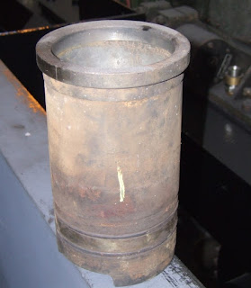
One of the original liners
The liners were all badly corroded and were too far gone to be honed.  However the pistons seemed in good condition, although the rings were all gummed up.  Most of the rings broke while trying to free them from the ring grooves.  The gudgeon pins and big end shells seemed in good condition.

The crankcase was badly "sludged" with black sooty deposits, because a non-detergent lubricating oil had been used, but that could easily be cleaned up using paraffin.  Because the big end bearings didn't seem worn, it was assumed that the main bearings were OK as there wasn't any sign of movement.  Examination of the main bearings would require removal of the flywheel and lifting the engine block from the chassis - a lot of work.

The cylinder heads seemed basically OK, but would need a complete clean and de-coke.  The rockers seemed OK although it was noted that one of them had been repaired by brazing.  It was a good repair, but if a new rocker could be found, it would be replaced.

Exhaust rocker with brazing repair

On removing the valves, the exhaust valve of head no. 1 was found to be severely pitted by the water ingress, and could not be ground back into shape.  The valve seat was also too badly pitted to be ground in and would need a new cast-iron insert fitted.  All the other valves were capable of being ground in.

Badly pitted exhaust valve
All the cylinder head studs were found to be very wasted due to corrosion, and would need to be replaced.  One of the covers for the water jacket had cracked due to freezing - it was simple to make a replacement and no other frost damage was found.  The water drain cock for the block was blocked with rusty sludge and there was a lot of sludge in the water galleries.  The injectors were unlikely to work after being inactive for so long and one of the nozzles had become very badly pitted and would probably need replacing while the other water-damaged nozzle was not too bad and might be salvageable.

The dismantled engine
So the following replacement parts would be required :-
  1. 4 off cylinder liners & seals
  2. 4 off head gaskets
  3. 4 off piston ring sets
  4. 1 off exhaust rocker
  5. 1 off exhaust valve